Concrete Barrier Installation in the UAE: The Step-by-Step Method Statement RTA Inspectors Approve
The difference between a barrier run that passes inspection in fifteen minutes and one that is rejected on the spot is rarely the barrier itself. It is the sequence of work. The barriers are often the same units, from the same yard, in the same condition. What differs is the ground preparation, the placement order, the connections and the evidence available at the time the inspector arrives.
This guide sets out the installation sequence we recommend to contractors for RTA-region works in Dubai and for DMT projects in Abu Dhabi, together with the checks that inspectors apply in practice.
Before the First Unit Is Lifted
Confirm the Documentation
Installation follows approval, not the reverse. Before plant is mobilised, confirm that the traffic management plan is approved, the permit or NOC is valid for the road in question, and the barrier type, profile and run length match what the drawing shows. Installing a different unit to the approved drawing is treated as a non-conforming installation and is one of the most common sources of fines, as set out in our RTA compliance and fine review.
Survey the Line
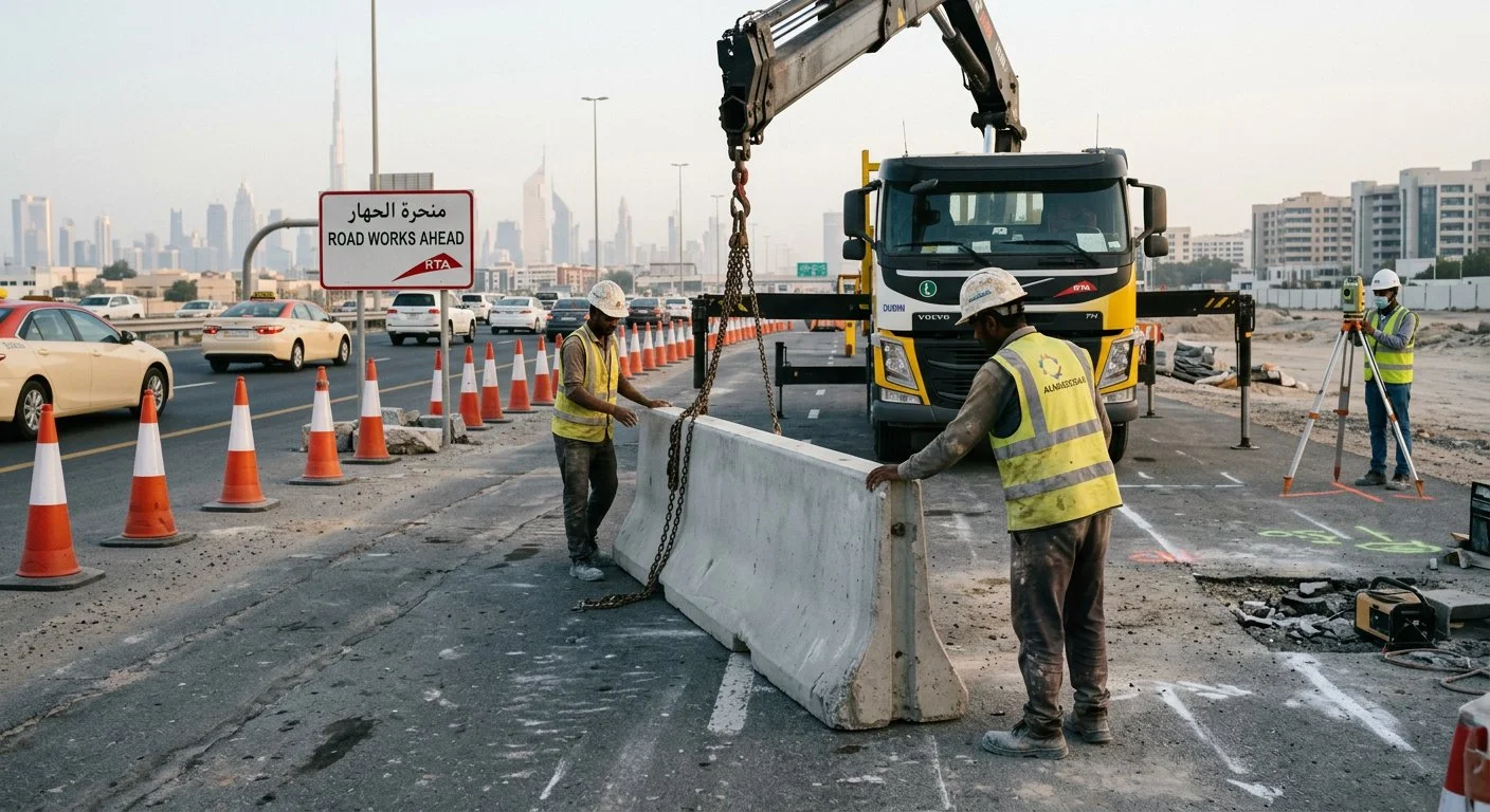
Set out the barrier line with the surveyor before delivery. Mark the centre line at intervals, mark the start and end of the run, and mark the position of every access gate and crossing point. A barrier line set out after unloading always takes longer and seldom lands accurately.
Two measurements govern the setting out. The buffer zone, typically a minimum of 0.6 m clear behind a freestanding concrete run, and the flare at each traffic-facing end, calculated at 15:1 for 80 km/h roads and 20:1 for 100 km/h roads, or replaced with a crash cushion where flaring space is not available.
Inspect the Ground
Barriers are freestanding units carried on their own base. Uneven or soft ground produces joints that open, units that rock and a run that fails the visual check. Three points to verify:
- The bearing surface is hard and compacted, with no loose material or fresh backfill along the line
- The surface is free of significant steps between asphalt and verge, or the step is bridged with bearings
- Drainage and stormwater paths are not blocked by the run
Where a trench runs parallel to the barrier line, place the run on the carriageway side rather than on backfilled ground. Settlement behind a recent excavation is the principal cause of joint gaps that appear in the days after installation.
Prepare Utilities and Services
For works in the road reserve, confirm that utility clearances have been obtained and that no service covers will be trapped behind the line. Where drainage channels cross the barrier line, plan a controlled gap with a cover detail rather than bridging the channel with the barrier base.
Delivery, Offloading and Site Layout
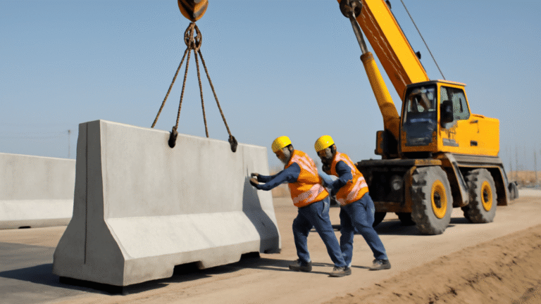
Deliveries are scheduled as clustered loads. Arrange the offloading sequence so that units are placed as close to their final position as possible; each additional handling cycle increases the probability of edge damage and consumes crane time.
A practical offloading plan:
- Deliver to the traffic-facing end of the run first, and place those units into position directly from the truck where access allows.
- Offload and stock only the units required later in the programme, on level ground with timber dunnage, no more than two units high for 3 m lengths.
- Keep the lifting path clear of the excavation, of workers and of the travelling lanes.
- Preserve reflective markings during offloading with the protective arrangements agreed at order stage.
Lifting methods, equipment capacity and stacking limits are covered in detail in our barrier handling, lifting and storage guide.
The Placement Sequence
Step 1: Position the First Unit
Start at the upstream end of the traffic-facing run, in the direction of approaching traffic. Align the first unit to the survey line and check it in both directions: longitudinal alignment along the run and plumb across the base. This unit sets the geometry for the remainder of the line. A first unit placed out of line will propagate the error along the run.
Step 2: Connect Each Unit as You Go
Place the second unit tightly against the first and confirm the connection. Three connection types are in use on UAE projects:
| Connection Type | Description | Where Specified |
|---|---|---|
| Pin and loop | Cast-in steel loops at each end, joined with a steel pin | Standard for temporary and semi-permanent runs |
| Male and female interlock | Tongue and groove cast into the end faces | Site lines and lower-speed applications |
| Bolt-through plates | End plates connected with threaded bar | Permanent medians |
Every joint must be connected. RTA treats an unconnected run as a series of individual units, which changes the containment assessment of the installation. Leave gaps of no more than 50 mm at joints, and address any vertical step greater than 25 mm by correcting the bearing, not by forcing the connection.
Step 3: Maintain Alignment Along the Run
Check alignment at every fifth unit rather than only at the end. On curves, use shorter units or step the line, accepting that a 3 m unit pulled to a tight radius will open a gap at the toe. For radii below 100 m, 2 m units produce a smoother chord and are less prone to gaps, a point covered in our barrier quantity and takeoff guide.
Step 4: Set the Flare and Buffer
At the traffic-facing end of the run, set the flare to the rate required by the approved plan. Confirm the buffer zone behind the run is clear of materials, plant and personnel, and that no excavation is open within the deflection distance. Freestanding concrete units deflect on impact within a defined zone, and that zone must remain free.
Step 5: Anchor or Pin Where Specified
Where the drawing specifies anchoring, typically at bridge decks, on high-speed runs, or where the working width must be minimised, install the anchors or pins to the detail shown. Keep the drilling record and the anchor type documentation for the inspection file.
Step 6: Fix Markings and Lighting
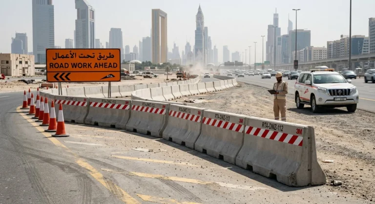
Reflective markings on road-facing runs are inspected as part of the installation. Confirm that panels are fitted at the specified height, are clean, and are correctly oriented for approaching traffic. Where night works are in progress or the run remains in place overnight, check the lighting and the delineation along the full length before leaving the site.
Final Checks Before You Call the Inspector
The following checklist reflects the points inspectors verify in practice. Completing it before the call converts most inspections into a short visit.
| Check | Pass Criteria |
|---|---|
| Permit and approved plan on site | Current drawings available, physical or digital |
| Run matches the approved drawing | Profile, length and position aligned to the plan |
| Joint gaps | No gap exceeding 50 mm |
| Connections fitted | Every joint connected per specification |
| Alignment | Line consistent, no step above 25 mm |
| Plumb | Each unit vertical, no rocking |
| Flare and taper | Rate correct for the posted speed |
| Buffer zone | Clear of materials, plant and personnel |
| Reflective markings | Fitted, clean and at the correct height |
| Anchoring, where specified | Installed to detail, records retained |
| Photographs | End treatment, joints, markings and full run recorded |
Photographic records carry more weight than most contractors expect. A dated set showing the flare, a joint with a tape measure alongside it, the reflective markings and the completed run resolves most queries without a return visit.
Common Installation Failures and Their Causes
| Failure | Root Cause | Prevention |
|---|---|---|
| Rejection for incorrect profile | Order placed before the TMP was approved | Confirm profile against the approved drawing |
| Joints open within days | Barrier line placed over backfill or soft ground | Set out on hard standing; place on the carriageway side of trenches |
| Run out of alignment | First unit set without survey | Set out and verify the first unit in both directions |
| Gap at flare | Flare calculated after delivery | Calculate the flare during setting out and order the additional units |
| Markings rejected | Panels dirty, faded or at the wrong height | Inspect and clean markings before calling the inspection |
| Damage during installation | Chains or slings used across finished faces | Use clamp or certified lifting points |
Where the barrier line is protecting an open utility trench, the run and the covers are inspected together. Load-rated covers, their classes and the bearing requirements are covered in our trench cover load rating guide for DEWA and RTA works.
Where Concrete and Plastic Systems Interface
On many sites, the traffic-facing side is concrete and the internal or pedestrian side is a plastic channelizing system. The interface is where inspections often focus, because it is where the two systems change category. The rules on which system is accepted at which speed and depth are set out in our comparison of plastic and concrete barriers.
Frequently Asked Questions
How long does it take to install a concrete barrier run?
With the line surveyed, the ground prepared and a Hiab on site, a two-person crew with a plant operator places approximately 40 to 60 units of 3 m in a working day, equating to 120 to 180 linear metres including connections. Preparation, not placement, determines the total programme.
Do barriers have to be pinned or anchored?
Not always. Freestanding concrete runs are accepted on many roads and in most temporary applications, provided the buffer zone is maintained and the end treatment is correct. Anchoring or pinning is specified where deflection must be limited, such as on bridge decks, in constrained working widths, or on high-speed permanent installations. Follow the drawing.
What gap is acceptable between barrier units?
Manufacturers design for a small installed gap. Keep joints to no more than 50 mm and ensure each joint is connected. Larger gaps, or gaps at the toe on curves, are treated as defects because they can be caught by a wheel and can permit pedestrian access.
Can barriers be installed before the permit is issued?
No. Placement in the road reserve without a valid permit exposes the contractor to penalties and removal orders regardless of the quality of the installation. Programme delivery against the permit window, not ahead of it.
What documentation should be kept on site?
The approved traffic management plan, the permit or NOC, delivery notes with batch references, the concrete strength reports for the delivered units, the anchoring records where applicable, and dated photographs of the completed installation.
Installation Support from Arab Precast
We supply barriers with the documentation package prepared for submissions, deliver on Hiab-equipped trucks for direct placement where site access allows, and can provide setting-out guidance for projects over 100 linear metres, including flare quantities and truck sequencing.
To plan an installation, send the site location, the approved or draft TMP drawing, and the programme dates through our contact page or WhatsApp +971 58 660 9400. Product data is on the precast concrete barriers page, and further method guidance, including municipality requirements and profile selection, is available on our blog.